Ok so the instructions I am going to give are for installing Neons/LEDs to come on when your doors open in the same manner your roof lights do. To do this you will need some basic skills soldering and depending on the method of connecting you chose know how to use electrical lugs. Materials Required:
*Fuse (Say a 3A fuse for a few LED or neon lights) and fuse holder (not a must have, but definitely recommended as I have no idea what sort of fused protection if any that mitsu has put on the wire you will be tapping for power)
*3 position switch (ON-OFF-ON type)
*Soldering iron
*Solder
*Pliers and a wire stripper if you wish
*Drill and drill bits
*Small cable ties
*Electrical tape The switch and fuse holder can be obtained from Jaycar or *Richard* Smith.
Here is a diagram for the electrical circuit we are making:
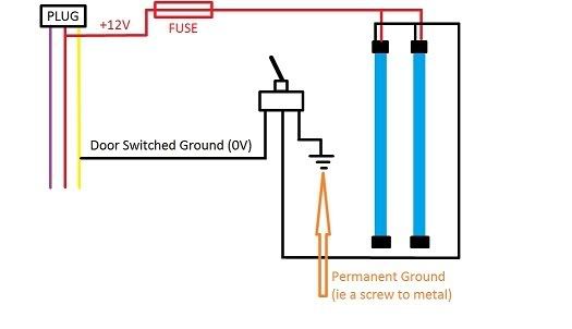
From this you will note its the ground that the car switches for the doors opening, which to me seemed odd but I imagine it does this as it will be a transistor or relay inside the ETACs that controls this I believe..... I have used a red line to show the + wire of the neons and a black line to show the - wire of the neons, in the step below we'll work out which is which on the wires to the LED/neons. If your neons have a ciagrette lighter plug attached you will need to cut it and work out the polarity of the wires (one tends to be black and the other black with a white stripe).
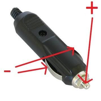
For this you'll need a multimeter ($20ish for a basic one from *Richard* smith) and use the following picture below to test between the highlighted points on the plug and the wires to determine which is which.
The plug we are going to tap into is located behind the glove box (I presume by now most of us know how to do this??? I might look at making a DIY for this).
Here is a picture:
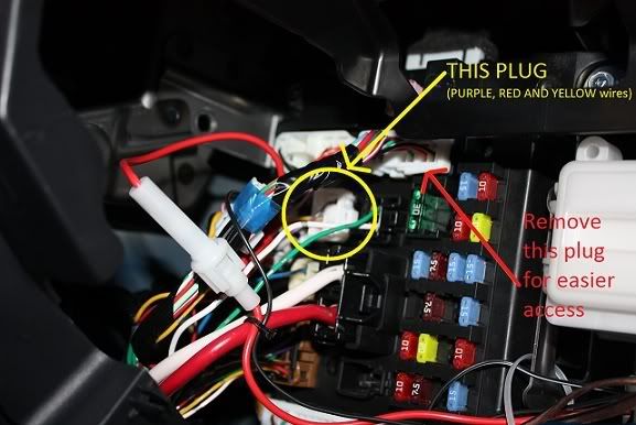
Removing that large plug as indicated makes access to the plug we want much easier. To ensure it is the right plug, turn on your dome light to "DOOR" and when you unplug the 3 wire plug that is circled you will find that roof dome light should go out.
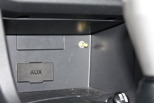
Here is a close up of the plug:
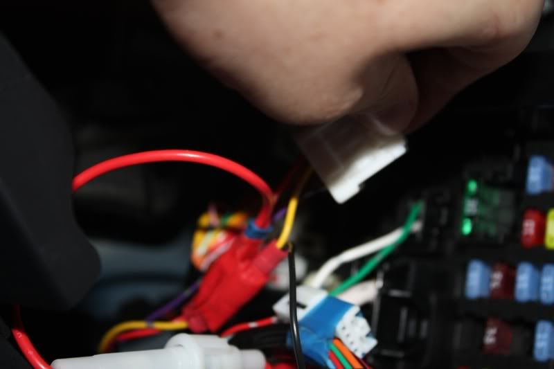
If you do these next steps with the above plug removed from its socket there will be no need to disconnect the battery. Now connect the ground (0V) as shown in the diagram to the yellow wire. To do this you can strip back the insulation to solder it on (rather tight space for soldering though) or you can cut the wire and then use electrical auto lugs to join it back together with the wire to the neons included. If you have never done this sort of stuff before I highly recommend practicing on some scrap wire first or find a mate who can do it. Similarly attach one end of the fuse to the red wire from the plug and attach the other end of the fuse to the positive wire for your neons as per my first diagram. Now choose a location for your switch. i decided to place mine in the centre console as to the front seat passenger and driver it is out of view
To put that in you need to remove the stereo and then use an appropriately sized drill bit to drill a hole. Now you no where you switch will be bring the wires necessary to it and solder them to the back of the switch. Always remember to use a old towel to catch any stray solder when soldering inside your car and as a safety precaution you should try and minimize contact with solder and wash your hands immediately after as solder has high concentrations of lead. Lastly remember to use electrical tape on ALL connections to keep them from short circuiting and use cable ties where appropriate. Email me for larger pictures if required.
Note it has been confirmed that the ES uses Solid Black, and Black with white stripes instead of the yellow and red wires like the VR/VRX. The black color with white stripe is (+) and black color is (-)
*Fuse (Say a 3A fuse for a few LED or neon lights) and fuse holder (not a must have, but definitely recommended as I have no idea what sort of fused protection if any that mitsu has put on the wire you will be tapping for power)
*3 position switch (ON-OFF-ON type)
*Soldering iron
*Solder
*Pliers and a wire stripper if you wish
*Drill and drill bits
*Small cable ties
*Electrical tape The switch and fuse holder can be obtained from Jaycar or *Richard* Smith.
Here is a diagram for the electrical circuit we are making:
From this you will note its the ground that the car switches for the doors opening, which to me seemed odd but I imagine it does this as it will be a transistor or relay inside the ETACs that controls this I believe..... I have used a red line to show the + wire of the neons and a black line to show the - wire of the neons, in the step below we'll work out which is which on the wires to the LED/neons. If your neons have a ciagrette lighter plug attached you will need to cut it and work out the polarity of the wires (one tends to be black and the other black with a white stripe).
For this you'll need a multimeter ($20ish for a basic one from *Richard* smith) and use the following picture below to test between the highlighted points on the plug and the wires to determine which is which.
The plug we are going to tap into is located behind the glove box (I presume by now most of us know how to do this??? I might look at making a DIY for this).
Here is a picture:
Removing that large plug as indicated makes access to the plug we want much easier. To ensure it is the right plug, turn on your dome light to "DOOR" and when you unplug the 3 wire plug that is circled you will find that roof dome light should go out.
Here is a close up of the plug:
If you do these next steps with the above plug removed from its socket there will be no need to disconnect the battery. Now connect the ground (0V) as shown in the diagram to the yellow wire. To do this you can strip back the insulation to solder it on (rather tight space for soldering though) or you can cut the wire and then use electrical auto lugs to join it back together with the wire to the neons included. If you have never done this sort of stuff before I highly recommend practicing on some scrap wire first or find a mate who can do it. Similarly attach one end of the fuse to the red wire from the plug and attach the other end of the fuse to the positive wire for your neons as per my first diagram. Now choose a location for your switch. i decided to place mine in the centre console as to the front seat passenger and driver it is out of view
To put that in you need to remove the stereo and then use an appropriately sized drill bit to drill a hole. Now you no where you switch will be bring the wires necessary to it and solder them to the back of the switch. Always remember to use a old towel to catch any stray solder when soldering inside your car and as a safety precaution you should try and minimize contact with solder and wash your hands immediately after as solder has high concentrations of lead. Lastly remember to use electrical tape on ALL connections to keep them from short circuiting and use cable ties where appropriate. Email me for larger pictures if required.
Note it has been confirmed that the ES uses Solid Black, and Black with white stripes instead of the yellow and red wires like the VR/VRX. The black color with white stripe is (+) and black color is (-)